What Information Is Stored in TCP's Header?
From packet switching to checksums — everything about the TCP header

In my previous post, Why Did HTTP/3 Choose UDP?, I briefly touched on TCP, but that post focused on what problems TCP had that led HTTP to move away from it. This time, I want to focus more on TCP itself.
I originally planned to cover all of TCP in a single post, but the sheer volume of material forced me to split it into several posts. (This grandpa protocol just never ends no matter how deep you dig…)
So in this post, I’ll focus exclusively on the fields inside TCP’s header and what they mean.
TCP, Transmission Control Protocol
TCP (Transmission Control Protocol) is a protocol used at the transport layer of the OSI 7-layer model. Its purpose is to ensure that information is exchanged reliably, in order, and without errors between devices.
In computer science, things closer to the machine are described as “lower” or “behind,” while things closer to humans are “higher” or “in front.” The OSI model works the same way — lower layers are closer to the hardware, and higher layers are closer to people.
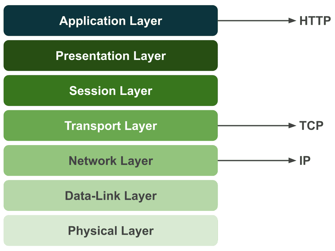
Protocols we’re familiar with — like HTTP (Hypertext Transfer Protocol), SMTP (Simple Mail Transfer Protocol), and FTP (File Transfer Protocol) — sit at the highest layer, the application layer. In contrast, lower-layer protocols like TCP, UDP, and IP are ones we encounter far less often.
That’s because the OS handles most of these for us. Developers programming at higher layers don’t need to worry about every detail of what happens down below.
This is one of the reasons the layered model exists in the first place. Networking is a convergence of countless technologies, and no single developer can know everything. Through strict separation of responsibilities between layers, the scope of what you need to worry about for any given task is narrowed down.
Thanks to this, when using HTTP, we don’t need to simultaneously think about which DNS server to use or how to process packets.
That said, even with these clear layer boundaries, if you have zero knowledge of what happens in the lower layers, you might encounter situations where everything looks fine at the application layer but a lower-layer issue leaves you completely helpless.
For this reason, I think it’s worth knowing at least the general workings and overview of the protocols you use. So with this post, I want to crack open TCP — a protocol I previously only knew through a handful of high-level characteristics.
Why Was TCP Created?
Personally, when studying any technology, I find it far more effective to understand why it was needed and empathize with that reasoning, rather than just memorizing facts.
TCP is old enough that it’s hard to fully relate to the circumstances of its creation, but looking at why this protocol was developed reveals the struggles engineers faced back then.
A Network That Survives Nuclear War
As I just mentioned, TCP was developed as part of ARPANET, a project by the U.S. Department of Defense during the Cold War in the 1970s. One of the key topics of interest during ARPANET research was “a network that survives even nuclear war.” (The opponent in said nuclear war being, of course, Mother Russia…)
The reason was that 1970s networks used circuit switching. If a relay station took a direct hit and was destroyed, or if a single connecting line was cut, communication would be severed entirely.
 I wasn't there personally, but I imagine it looked something like this...?
What relay stations did back then was essentially this: when A asked the station to “connect me to B,” the operator would find the jacks labeled A and B on a patch panel full of cables (like the photo above) and physically connect them with a cable.
Literally switching circuits. If A then wanted to talk to C instead, you’d unplug the cable from B’s jack and plug it into C’s.
With circuit switching, you physically hold one dedicated line for communicating with your counterpart, which means circuit utilization is inherently low. It’s the same principle as getting a “the person you’re calling is currently on another call” message when you try to phone someone.
Of course, monopolizing a circuit has advantages — like being able to stream large amounts of data at high speed. But what mattered to the U.S. at the time was a connection that wouldn’t break even if a nuke went off, so depending entirely on a single circuit was a major drawback.
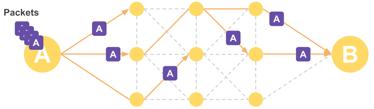
This led to the idea of packet switching. Instead of sending data through a single circuit — where a destroyed line or relay station means losing the data forever — the idea was to split data into small pieces and send them through multiple circuits. A kind of diversified investment, if you will.
 This way, even if one node is destroyed, not all data is lost
In the worst case, a destroyed circuit or relay station might cause some data loss, but as long as the entire network isn’t hit at once, the chance of losing all data is low. And since you’re not holding a dedicated circuit open — you just mark a destination on each packet and send it off — circuit utilization improves as well.
For these reasons, the Department of Defense adopted this idea for ARPANET. Early tests were a massive success, proving the practicality of packet switching.
ARPANET, initially used only by a handful of universities and military installations, was eventually opened to the public and grew into what we now know as the internet. Along the way, TCP — ARPANET’s communication protocol — rose to prominence with it.
Problems with Packet Switching
But packet switching wasn’t a silver bullet either; it had several problems. The concepts that always come along when studying TCP — ARQ, SYN, ACK, and so on — are the result of past engineers racking their brains to solve these very problems.
Q: What if a packet silently disappears or gets corrupted mid-transmission?
A: Then ask for just that packet to be resent! (ARQ)Q: The receiver needs to know the order the sender split the packets in to reassemble them, right?
A: Then send a sequence number along with each packet! (Sequence Number)Q: What if the sender sends packets faster than the receiver can process them?
A: Then have the receiver tell the sender how much it can handle and only send that much! (Sliding Window)
The many features and concepts TCP has might look complex and memorization-heavy on paper, but when you consider the situation at the time, you can see they were all absolutely necessary.
And since these features work by reading information in the header of the segments the other party sends, before examining each feature individually, I want to look at what information TCP’s header contains and what it all means.
Let’s Crack Open TCP’s Header
Protocols like HTTP, TCP, and IP each have their own roles, and they attach their own headers to the data being sent to represent information about that data.
Since TCP is responsible for transmission reliability, flow control, congestion control, and similar concerns, the TCP header contains various values needed to support these functions.
In other words, looking at the header gives you a quick overview of TCP’s features — which is why I chose header dissection as the first step in this TCP series.
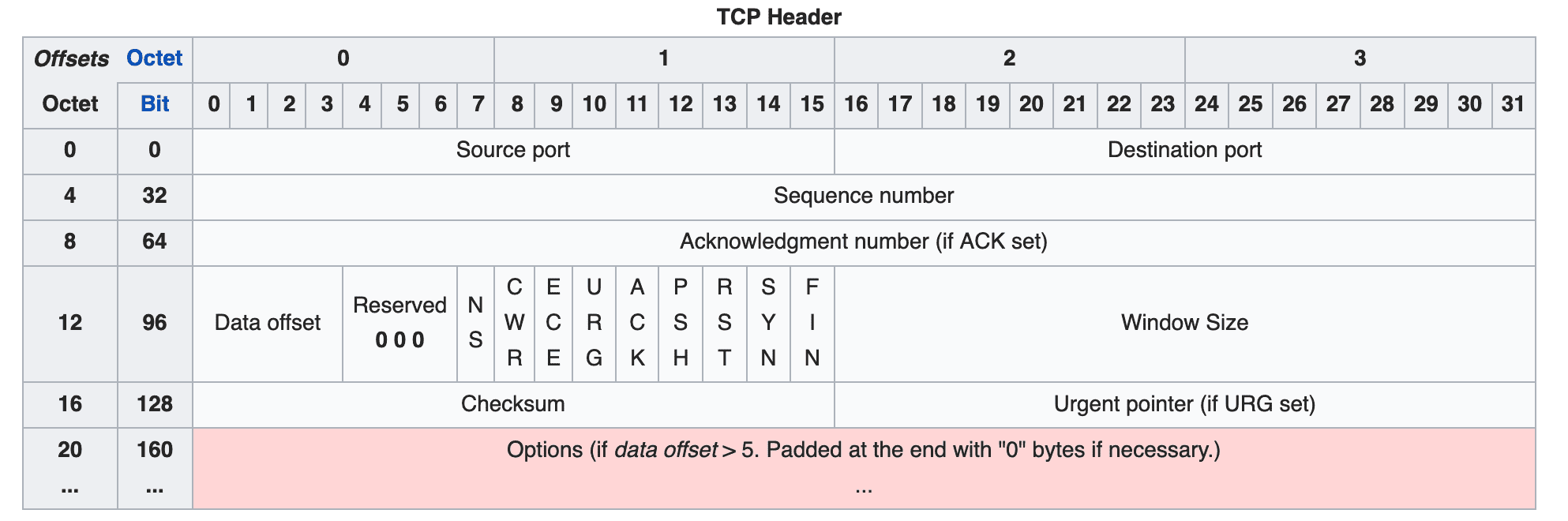
TCP uses a 20-byte (160-bit) header divided into multiple fields. Each field’s bits are set to 0 or 1 to represent information about the segment being transmitted.
However, 20 bytes is the size of a basic header with no options. When using TCP’s various options, additional option fields are appended to the end of the header, which can add up to 40 more bytes for a maximum of 60 bytes.
Let’s go through each field in the order shown in the diagram.
Source Port / Destination Port
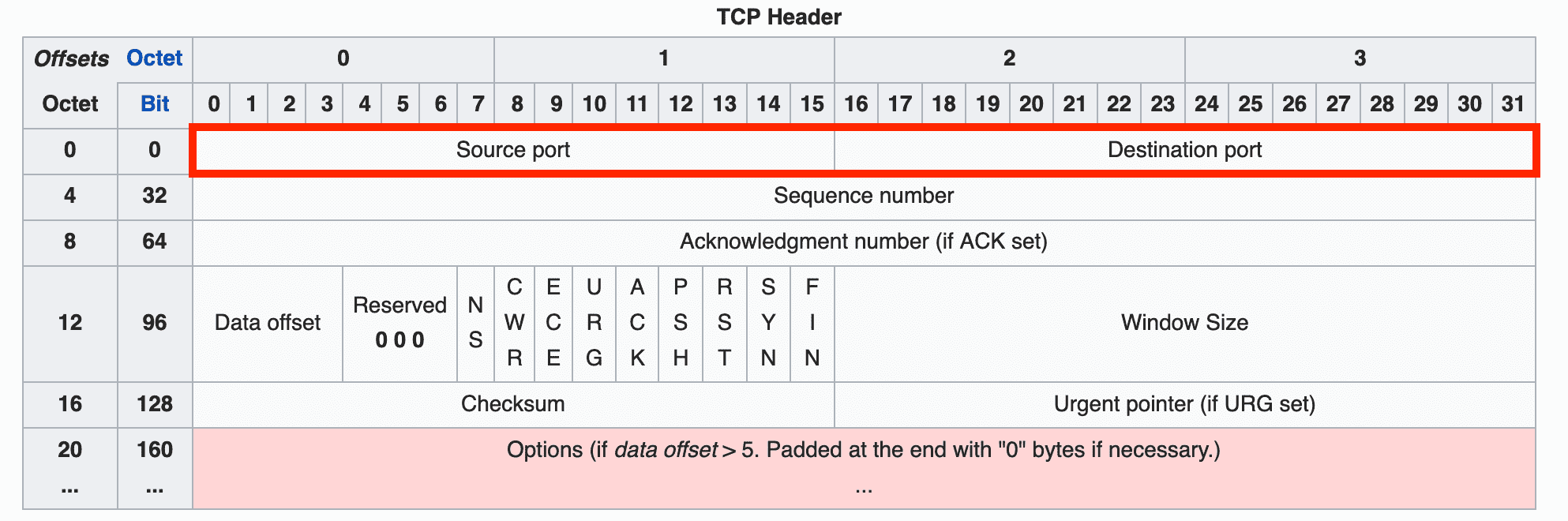
These fields indicate the source and destination of the segment, with 16 bits allocated to each. To identify the source and destination addresses, you need both an IP address and a port number.
Since the IP address naturally belongs in the IP header one layer below (the network layer), the TCP header doesn’t have an IP address field — only port fields.
Sequence Number
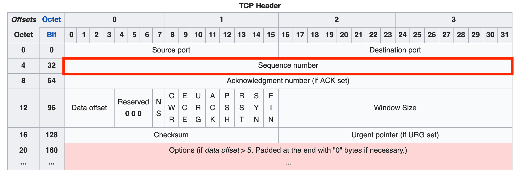
The sequence number indicates the order of the data being transmitted and is allocated 32 bits. It can represent values up to 4,294,967,296, so sequence numbers don’t duplicate easily.
Thanks to this sequence number, the receiver can determine the order of split segments and reassemble the data correctly.
When the sender transmits data for the first time, it initializes this number to a random value. After that, it increments the sequence number by 1 for each byte of data it sends. When the maximum value of 4,294,967,296 is exceeded, it wraps around back to 0.
Acknowledgment Number
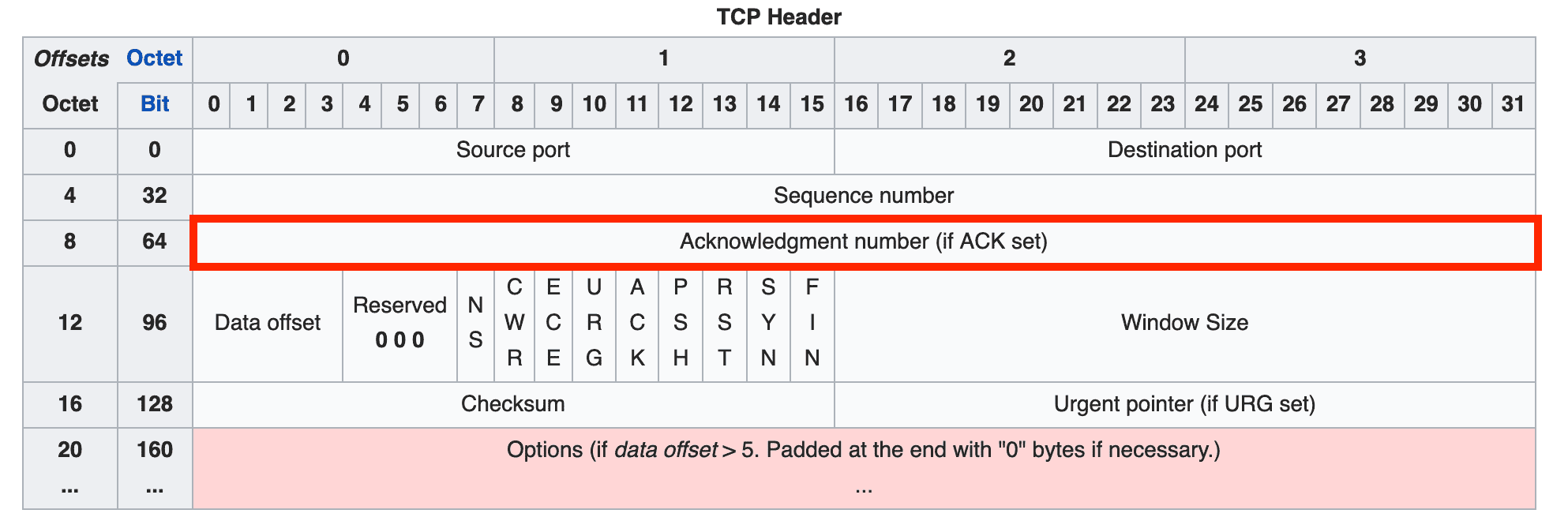
The acknowledgment number represents the next sequence number that the receiver expects, and is allocated 32 bits.
During the handshake process for connection setup and teardown, each side creates its acknowledgment number as the other party's sequence number + 1. But during actual data exchange, the acknowledgment number is calculated as the other party's sequence number + the number of bytes received.
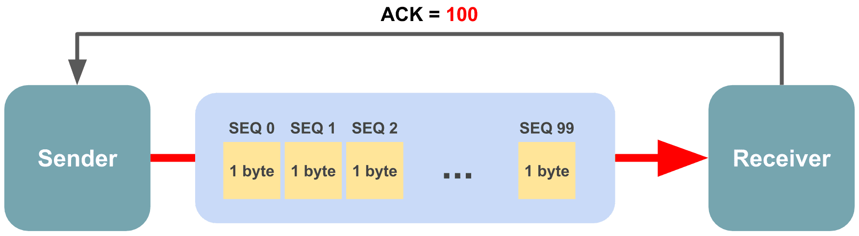
For example, imagine sending 1 MB of data. Since you can’t send such a large amount in one go, the sender must split it into multiple segments and transmit them incrementally. The amount of data the sender can transmit at once varies depending on the network and receiver’s state, but let’s assume it’s 100 bytes.
The sender transmits 100 bytes in the first transmission and initializes the sequence number to 0. Since the sequence number increments by 1 per byte, the first byte chunk gets 0, the second gets 1, the third gets 2, and so on.
So in this transmission, the receiver received 100 byte chunks numbered 0 through 99, and the sequence number it should expect in the next transmission is not 2, but 100.
 100 bytes are bundled into a single segment for transmission
If you capture packets using tcpdump, you can actually see the receiver’s acknowledgment number increasing by the length of data the sender transmitted.
localhost.http-alt > localhost.49680: Flags [P.], seq 160:240, ack 161, win 6374, length 80
localhost.49680 > localhost.http-alt: Flags [.], ack 240, win 6374
Looking at the sender’s segment, the sequence number shows seq 160:240, and the receiver uses the value after the colon as its acknowledgment number.
Here, the sequence number format represents a range of n inclusive : m exclusive. Since the number after the colon is not included in the sender’s sequence range, the receiver can use it directly.
In other words, the acknowledgment number indicates the starting point of the data that should be sent next.
Data Offset

The data offset field indicates where the actual data (as opposed to the header) begins within the segment.
This offset is expressed in 32-bit word units, where 1 word = 4 bytes in a 32-bit system. Multiplying this field’s value by 4 gives you the starting position of the actual data after the header.
The 4 bits allocated to this field can represent values from 0000 to 1111, meaning 0 to 15 words, which translates to 0 to 60 bytes. However, since all fields except options are mandatory, the minimum value is fixed at 20 bytes (5 words).
This field is needed because the Options field, described below, has a variable length.
Reserved (3 bits)
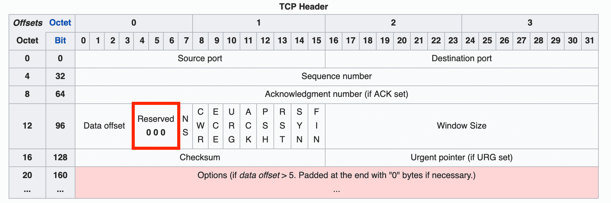
A field reserved for future use — all bits must be set to 0. You can see it marked as 0 0 0 in the header diagram above.
Flags (NS through FIN)

Nine bit flags that indicate the properties of the current segment. Originally there were only 6 flags, but NS, CWR, and ECE were added using bits from the Reserved field to improve congestion control.
Here are the original flags and their meanings:
| Field | Meaning |
|---|---|
| URG | Indicates that the Urgent Pointer field contains a valid value. Data pointed to by this pointer is given high priority and processed first. Rarely used today. |
| ACK | Indicates that the Acknowledgment Number field contains a valid value. If this flag is 0, the acknowledgment number field is ignored entirely. |
| PSH | Push flag. Requests that the receiver deliver this data to the application as quickly as possible. If this flag is 0, the receiver waits until its buffer is full. When this flag is 1, it also implies there are no more segments connected after this one. |
| RST | Reset flag. A request to forcefully reset the connection with a counterpart that is already in ESTABLISHED state. |
| SYN | Synchronize flag. Indicates this segment is for synchronizing sequence numbers when establishing a connection with the other party. |
| FIN | Finish flag. Indicates this segment is a request to terminate the connection with the other party. |
The newly added NS, CWR, and ECE flags (carved out of the former Reserved field) are used for Explicit Congestion Notification (ECN).
Before ECN, the conventional method for detecting network congestion relied on timeouts. But for latency-sensitive applications, even that waiting time was too costly, so a special mechanism was needed to explicitly notify senders and receivers of congestion — and that’s ECN.
The CWR, ECE, ECT, and CE flags are used to inform the other party about congestion. Of these, CWR and ECE reside in the TCP header, while ECT and CE are in the IP header.
| Field | Meaning |
|---|---|
| NS | A field added in RFC 3540 to guard against the CWR and ECE fields being accidentally or maliciously concealed. |
| ECE | ECN Echo flag. When this field is 1 and the SYN flag is also 1, it signals to the other party that ECN is supported. If the SYN flag is 0, it’s a request to reduce the segment window size because the network is congested. |
| CWR | Indicates that an ECE flag has already been received and the sender has reduced its segment window size. |
ECN is a separate topic from this post, so if you’re curious, I recommend looking into the details through other resources.
Window Size
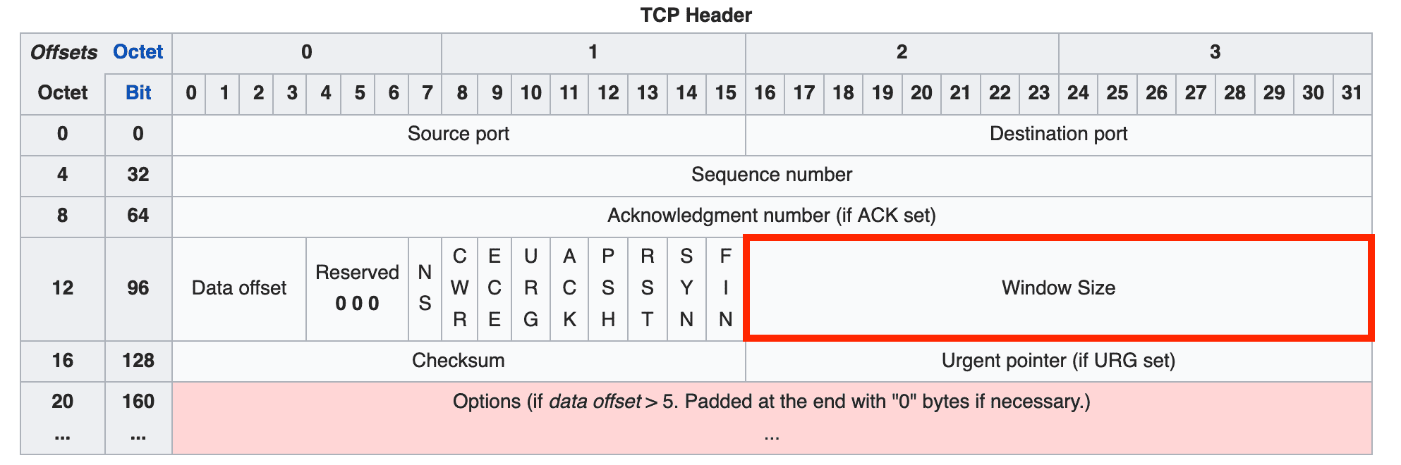
The window size field contains a value representing the amount of data that can be transmitted at once. It can express values up to , and since the unit is bytes, the maximum window size is 64KB.
However, this maximum was set long ago and doesn’t always fit today’s high-capacity, high-speed communication environments. So a method of left-shifting the bits to increase the maximum window size is also used, with the number of shifts specified using the WSCALE field in the options.
Checksum
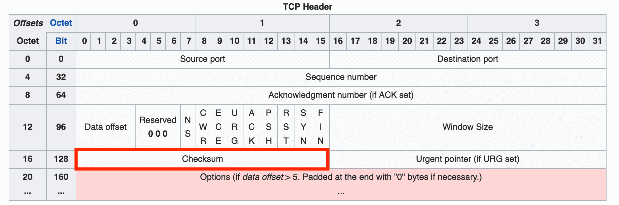
The checksum is a value used to detect errors that may occur during data transmission.
TCP’s checksum is generated by dividing the data to be transmitted into 16-bit chunks and adding them sequentially. The method is simple, but since looking at 16-bit additions would make the numbers painfully long, let me demonstrate with a simpler 8-bit example.
  11010101
+ 10110100
-----------
 110001001
Oops — adding two 8-bit numbers produced a 9-bit result with an extra digit. This overflow can’t fit in the checksum field.
This extra digit that appears when adding two numbers is called a carry. Just take that carry bit, detach it from the result, and add it back:
  10001001
+        1 (the overflowed bit)
-----------
  10001010
This technique is called wrap-around. Now take the one’s complement of the final result, and you have the checksum. “One’s complement” might sound fancy, but it just means flipping all the bits.
10001010
01110101 (after taking one's complement)
Now 01110101 is the checksum for this data. In this example I used 8 bits, so an 8-bit checksum came out. In practice, the data is split into 16-bit chunks for this process, producing a value that fits perfectly into the 16-bit checksum field.
The receiver, upon receiving the data, goes through the same process but stops before taking the one’s complement — at the value 10001010. It then adds this value to the checksum sent by the sender. If all bits are 1, the data is considered valid.
  10001010
+ 01110101
-----------
  11111111
If even a single bit is 0, it indicates that something was altered in the data the sender transmitted.
Urgent Pointer
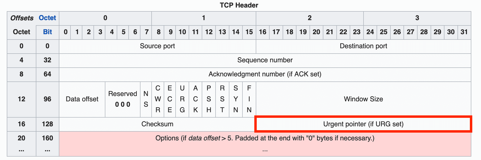
As the name suggests, this is an urgent pointer. If the URG flag is 1, the receiver prioritizes the data that this pointer references.
Options
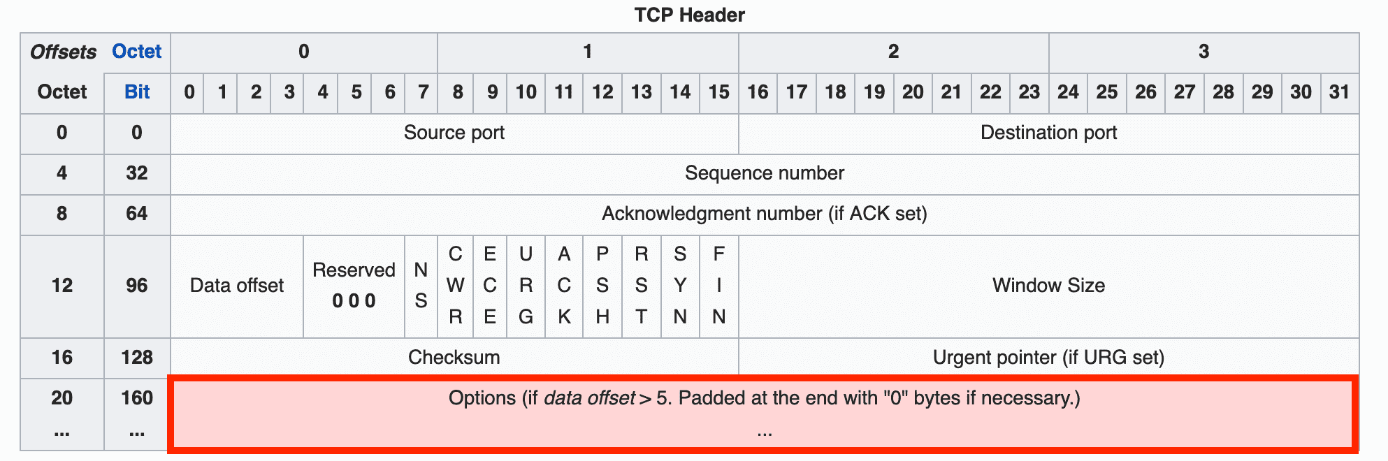
The options field contains fields used to extend TCP’s functionality, and its length is variable rather than fixed. This is why the data offset field described above is needed — so the receiver can tell where the header ends and the data begins.
I mentioned that the data offset field can represent values from 20 to 60 bytes. The header without any options — from Source Port through Urgent Pointer — is 20 bytes, and the maximum length of the options field is 40 bytes.
If the data offset field’s value is greater than 5 (20 bytes) but no TCP options are being used, the excess bytes must be filled with zeros so the receiver can correctly determine the header size.
Notable options include WSCALE for extending the maximum window size, SACK for using the Selective Repeat method, and roughly 30 other options — far too many to explain one by one here.
Wrapping Up
That covers a brief TCP overview and its header structure. Admittedly, this only scratches the surface of TCP, but given that this is a nearly 50-year-old protocol, there’s far too much content to fit into a single post.
As I mentioned at the start, protocols like TCP and IP are ones you rarely interact with directly unless you’re doing socket programming.
But even without direct interaction, as a web developer who uses HTTP every day, I think it’s worth knowing how the protocols underlying your daily work actually operate.
If you want to see how TCP is implemented in the kernel, you can check out the implementations in linux/net/ipv4 in the Linux source on GitHub. (Fair warning — the Linux source itself is so massive that cloning it takes ages.)
If you’d like to observe TCP communication firsthand, you can use a simple TCP example program along with utilities like tcpdump and netstat. Use tcpdump to inspect the content of packets exchanged between client and server, and netstat to check the TCP states of the client and server.
In the next post, I’ll cover TCP’s handshake process, flow control, and congestion control mechanisms.
That concludes this post on what information is stored in TCP’s header.
관련 포스팅 보러가기
How TCP Creates and Terminates Connections: The Handshake
Programming/NetworkSharing the Network Nicely: TCP's Congestion Control
Programming/NetworkTCP's Flow Control and Error Control
Programming/NetworkWhy Did HTTP/3 Choose UDP?
Programming/NetworkThe Path from My Home to Google
Programming/Network