[Making JavaScript Audio Effectors] Creating Your Own Sound with Audio Effectors
Like Logic Pro, Pro Tools? Implementing audio effects on the web
![[Making JavaScript Audio Effectors] Creating Your Own Sound with Audio Effectors](/static/026a9fe9c894f201ec1e45217221447c/b384d/thumbnail.webp "[Making JavaScript Audio Effectors] Creating Your Own Sound with Audio Effectors")
In this post, following the previous post, I’ll write about actually making audio effectors using the HTML5 Audio API.
As already mentioned in the previous post, the Audio API has the basic concept of creating audio flow by connecting multiple nodes, and provides some abstracted nodes needed for making effectors by default, so it’s not that difficult.
We just need to know what role each effector we want to make plays, what principles it has, and what purposes it’s used for. Since there are extremely many types of effectors used in audio, we can’t make all effectors - I’m thinking of implementing about 5 basic, most commonly used effectors.
The process of loading audio and creating a source node was already explained in the previous post, so I won’t explain it separately. This post starts explaining directly from implementing effectors. For all effectors, I’ll first briefly explain what that effector does and its principles, then dive straight into implementation without further ado.
So let’s tear into them one by one.
Compressor
A compressor is an effector that acts like a compressor, pressing down sound when it gets above a certain size to make it small again. Effectors that adjust sound size like this are called dynamic effectors.
When using audio sources, many start mixing with a compressor applied by default to defend against clipping that occurs when audio signals suddenly get above a certain size. But one question might arise here:
Wait, if you’re just preventing clipping, can’t you just reduce the gain?
Right. Actually, reducing gain can defend against clipping to some degree. But since music generally has dynamics, recklessly lowering gain creates the sad situation where quiet sounds don’t get inputted at all.
For example, imagine when you went to karaoke. Generally when singing ballads, you sing quietly with a calm feeling in the intro, then in the chorus the air pressure passing through vocal cords increases to hit high notes, making volume louder.
If you approach by recklessly lowering gain to record, you inevitably must match gain to the loudest sound - the belting in the chorus - and then the calm intro parts will barely get inputted.
 Varies slightly by singing technique, but this volume difference is bigger than you think
Here’s when you use a compressor to raise input gain to an appropriate level and compress sounds that are too loud, narrowing the gap between the intro’s quiet sounds and chorus’s loud sounds to match overall sound size.
 Compress signals exceeding the threshold to make them fall below it
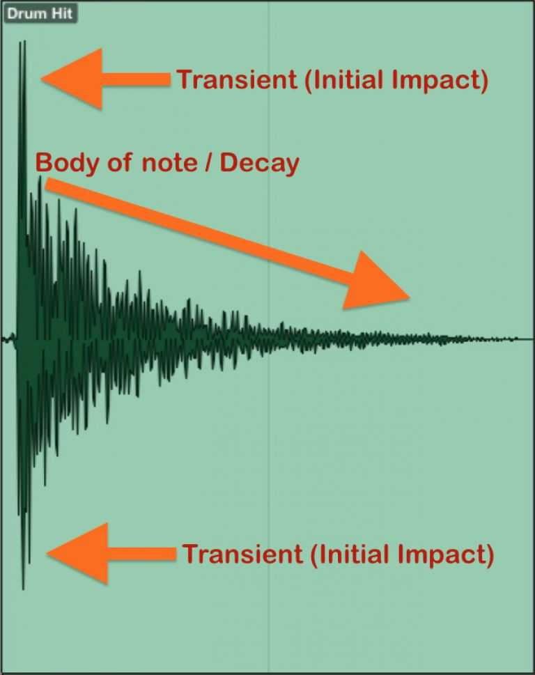
Also, I said compressors compress sound, but what compressing sound means might not be clear. A representative example is the clean “thud!”, “smack!” drum sounds we hear in typical music sources - that’s compressed sound. (These punchy sounds are usually called damping.)
Generally when recording drums, the characteristic reverb of the drum body resonating remains, but compressing this sound with a compressor can create the clean drum sound we typically hear.
Beyond that, using compressors on bass can give a solid feeling, pull distant sounds closer or vice versa - just using compressors well can give sound tremendously many feelings. That’s why the teacher who taught me sound engineering emphasized the compressor’s importance a lot.
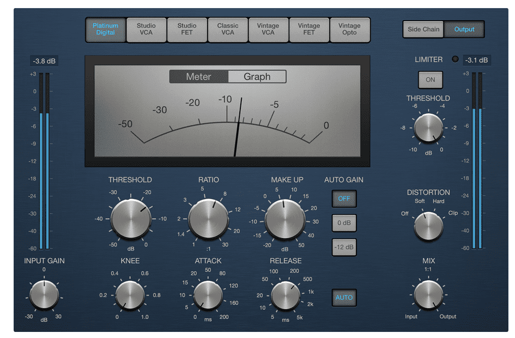
Compressors are designed to let you set things like when to start compressing signals and at what speed to compress using several values. The DynamicsCompressorNode provided by HTML5 Audio API provides these same values, so we need to know what these values mean to use this node properly.
Threshold
Threshold means the threshold that determines from what size to compress sound. Uses dB (decibel) as the unit.
Ratio
Ratio is the value determining what proportion sound exceeding the threshold will decrease by. Since this value means the input:output ratio, it’s generally talked about as ratios like 2:1, 5:1.
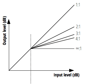
But the HTML5 Audio API property has slightly different units. The official docs say “dB value needed to change 1dB of output value” - just think assigning 12 to this property means compression ratio is 12:1.
Usually saying you applied compression moderately means about 4:1 ratio, so the default value of 12:1 for this property can be called quite hard compression.
Attack
Attack is the value determining how fast to compress sound. Think of it as determining how fast to hit and press down values exceeding the threshold.
Many people mistakenly think the attack time set here is “when attack starts,” but actually attack itself starts immediately when signal size exceeds threshold. The attack time we set is “time taken to reach the ratio set by Ratio.”
The unit usually uses milliseconds, but Audio API uses seconds.
Release
While attack was the speed of pressing sound, release is the value determining how fast to release compressed sound. The release value aims for time to reach the standard volume of 10dB, not the sound’s original size.
Like attack, release usually uses milliseconds as the unit but Audio API uses seconds.
Knee
Knee is actually a feature absent in most hardware compressors but quite often seen in software compressors. This value determines how naturally the compressor will be applied.
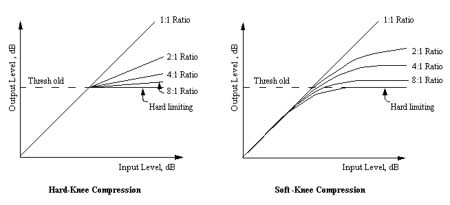
The bend degree in the graph above shows how gradually the compressor is applied. Compression applied quickly with a snap is called hard, while compression applied slowly is called soft.
Implementing Compressor
Actually as mentioned above, since HTML5 Audio API inherently provides DynamicsCompressorNode, we don’t need to directly implement the sound compression algorithm. We just need to create the node and connect it.
This time, instead of extracting audio buffers from user-uploaded audio files to create source nodes, I’ll proceed by extracting from <audio> tags to create source nodes. (This makes code much simpler) The source node created now will keep being used when implementing other effectors too.
const audioContext = new (AudioContext || webkitAudioContext)();
const audioDOM = document.getElementById('my-audio');
const sourceNode = audioContext.createMediaElementSource(audioDOM);

const threshold = -24;
const attack = 0.003;
const release = 0.25;
const ratio = 12;
const knee = 30;

const compressorNode = audioContext.createDynamicsCompressor();
compressorNode.threshold.setValueAtTime(threshold, audioContext.currentTime);
compressorNode.attack.setValueAtTime(attack, audioContext.currentTime);
compressorNode.release.setValueAtTime(release, audioContext.currentTime);
compressorNode.ratio.setValueAtTime(ratio, audioContext.currentTime);
compressorNode.knee.setValueAtTime(knee, audioContext.currentTime);

const inputGainNode = audioContext.createGain();
const outputGainNode = audioContext.createGain();

sourceNode.connect(inputGainNode);
inputGainNode.connect(compressorNode);
compressorNode.connect(outputGainNode);
outputGainNode.connect(audioContext.destination);
I created audio source flow in the order source > gain > compressor > gain - this is actually personal preference. But since most compressors generally have both input gain and output gain, I implemented the same way.
Playing the source node after this lets you hear compressed sound, but since non-sound-engineers struggle to feel subtle degrees of compression, I recommend changing the above values a bit extremely.
Reverb

Reverb is a spatial effector that gives sound a sense of space through resonance. What does giving a sense of space through resonance mean?
Actually, we can roughly determine by hearing sound whether the current space is wide or narrow, whether this space is made of rough walls or smooth space like glass. The difference is so subtle that untrained people struggle to notice.
How is this possible? Because of reverb from sound reflection. First, the principle of detecting space size by hearing sound is simple. After I shout “wah!” in a room, detect how long until the first reflected sound is heard.
But since this first reflected sound returns to me at extremely fast millisecond speeds, it’s not about counting 1 second, 2 seconds - you just feel it. This reflected sound is called early reflection.
But it doesn’t end there. Even after sound reflects once and reaches your ears, reflection will continue. These reverberations will bounce all around the space and reflect back to your ears.
 Green lines are early reflections, blue lines bouncing everywhere are reverb
Characteristics like how long this reverb is heard, how clearly it’s heard determine the room’s material. Just hearing the explanation makes detecting space by hearing sound seem impossible, but the music you normally hear already contains spatial design applying this principle.
Since reverb literally just needs to create reverb, some hardware reverbs use a method of putting materials like springs or metal plates inside equipment, playing audio to amplify reverb generated as materials vibrate. In other words, opening it up reveals just a spring or metal plate inside. (Creating good sound with such simple structure is scarier…)
However, implementing reverb in software is slightly different. Computers can’t generate natural analog signals like spring or metal plate vibrations, so they must implement through direct calculation. Software reverb divides into two main types: Convolution Reverb and Algorithm Reverb.
But since implementing both reverbs in this post would make it too long, I’ll reluctantly focus on convolution reverb. (Algorithm reverb alone is one post’s worth)
Convolution Reverb
Convolution reverb is a method of recording actual space reverb then synthesizing the reverb audio source and original audio source to add actual space resonance to the original audio source.
Briefly explaining a representative method of recording actual space reverb: play pure sine wave sounds continuously from low frequency to high frequency in the space you want to record, then record the resulting reverb.
 Recording space IR - Source: http://www.alanjshan.com/impulse-response-capture/
Since this reverb signal is called Impulse Response (IR), convolution reverb is also called IR reverb. The recorded IR gets merged to the original source through an operation called convolution.
If we start approaching this convolution concept mathematically, it gets headache-inducing and lengthens the post, so defining simply: just mixing different information together.
Since many readers of this post are probably developers, using machine learning more familiar to us to explain convolution, we could use CNN (Convolutional Neural Network) as an example learning algorithm.
In CNN too, when sending first layer images to the second layer, it mixes matrix-implemented kernels (or filters) and images to generate feature maps then sends to the next layer. Here you can think the first layer image and kernel information mixed.
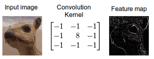 Mix original image and kernel to create new information - the feature map
Audio convolution reverb is the same. In this case, the information to mix just becomes the original source and IR.
Since convolution is a process multiplying the frequency spectrums of two audio sources - original source and IR - frequencies overlapping between the two sources get emphasized while non-overlapping frequencies decay. When overlapping frequencies between original source and IR get emphasized like this, the original source takes on the IR’s sound quality characteristics - that’s exactly convolution reverb’s principle.
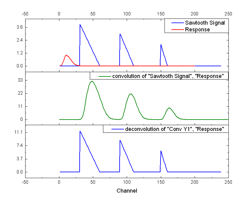 Original signal and recorded IR signal after convolution operation
Actually since HTML5 Audio API provides ConvolverNode that performs convolution operations instead, you can make convolution reverb without knowing what convolution is.
However, you need to at least know this effector has the principle of multiplying two signal information to create new signals to understand why I write such code, so I’m giving rough explanation.
Anyway, having grasped convolution reverb’s rough principles, let’s make it now.
Implementing Convolution Reverb
First, HTML5 Audio API doesn’t provide something like ReverbNode. But as explained above, since it provides ConvolverNode supporting convolution operations, we just need to directly create the reverb source IR (Impulse Response).
And since reverb is generally made to let you mix original source and reverb source according to ratio using wet and dry values, I’ll write code the same way.
const mix = 0.5;
const time = 0.01;
const decay = 0.01;
Explaining the 3 variables to use for reverb: mix means wet/dry ratio, time means reverb length, decay means reverb decrease speed. Now let’s directly generate IR using these values.
function generateImpulseResponse () {
  const sampleRate = audioContext.sampleRate;
  const length = sampleRate * time;
  const impulse = audioContext.createBuffer(2, length, sampleRate);

  const leftImpulse = impulse.getChannelData(0);
  const rightImpulse = impulse.getChannelData(1);

  for (let i = 0; i < length; i++) {
    leftImpulse[i] = (Math.random() * 2 - 1) * Math.pow(1 - i / length, decay);
    rightImpulse[i] = (Math.random() * 2 - 1) * Math.pow(1 - i / length, decay);
  }

  return impulse;
}
Looks complicated but tearing it apart reveals nothing much. sampleRate means the sample rate, i.e. sound quality, of the IR we want to generate, and length means sampleRate * time, i.e. buffer length for expressing reverb of time seconds.
Then just create one buffer node, generate random values from -1 ~ 1, raise 1 - i / length to the decay power and multiply by the just-generated random number. This makes values smaller as i increases, and smaller faster as decay increases. This expresses reverb decay. After that, pour these samples into the just-made buffer node and you’re done.
Expressing the IR buffer generated like this as a waveform would have roughly the following shape:
Ta-da, we simply generated IR like this. Now all that’s left is using ConvolverNode to synthesize the original source and this IR. Let’s first create the nodes needed to make the reverb effector’s audio flow.
const inputNode = audioContext.createGain();
const wetGainNode = audioContext.createGain();
const dryGainNode = audioContext.createGain();
const reverbNode = audioContext.createConvolver();
const outputNode = audioContext.createGain();
As explained above, typical reverb effectors provide the function of mixing and outputting original source and reverb-applied source using wet/dry values. Here the dry source must connect directly to outputNode for output without going through the reverb effector, while the wet source must go through our made reverbNode once and output to outputNode.
sourceNode.connect(inputNode);

// Connect dry source node
inputNode.connect(dryGainNode);
dryGainNode.connect(outputNode);
dryGainNode.gain.value = 1 - mix;

// Generate IR and input to Convolver's audio buffer
reverbNode.buffer = generateImpulseResponse();

// Connect wet source node
inputNode.connect(reverbNode);
reverbNode.connect(wetGainNode);
wetGainNode.connect(outputNode);
wetGainNode.gain.value = mix;

outputNode.connect(audioContext.destination);
We simply implemented convolution reverb like this. Actually what most affects convolution reverb quality is IR quality - since we made IR with roughly made sample audio, this reverb’s quality can’t be good. But playing and listening to the source node, you can amazingly hear that sound gained a sense of space.
If there’s a chance, I’ll post algorithm reverb implementation next time. Algorithm reverb is reverb implemented 100% with algorithm only, unlike convolution reverb which records and uses actual space reverb. So it feels slightly artificial but can give a feeling different from convolution reverb, so sound engineers understand these two reverbs’ characteristics and use them appropriately.
So for developers, algorithm reverb might actually be more understandable than convolution reverb, but unlike convolution reverb where you just need one ConvolverNode and a roughly made IR and the rest calculates automatically, algorithm reverb must truly be made from the ground up. So unfortunately I’ll post algorithm reverb next time.
If you’re curious about algorithm reverb implementation, you can check my GitHub repository.
Delay
Delay is the same spatial effector as reverb and can be thought similar since it repeats sound, but its principles and uses differ greatly.
First, delay is simply an effect repeating sound, but reverb mimics complex reflected sounds within space, so using delay alone makes expressing natural spatial feeling like reverb difficult.
The reverb effector we just made aims for realistic space expression so uses convolution or complex algorithms, but delay just needs to briefly delay the original source then play it again after seconds while gradually making sound quieter.
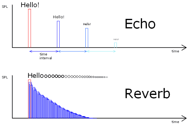 Difference between echo (delay) and reverb
Since delay has such simple principles, making it isn’t that difficult either.
Implementing Delay
HTML5’s Audio API provides DelayNode that delays and re-outputs input signals, so we can simply implement delay effectors using this node.
However, simply using DelayNode alone can only cause one delay, so we’ll implement delay using one trick. Let’s first declare variables needed for delay.
const mix = 0.5;
const feedback = 0.5;
const time = 0.3;
Like reverb, most delay effectors also have the function of mixing and outputting original source and delayed source using wet/dry values, so I’ll implement the same way. And the feedback variable is the volume to decrease when the original source delays once, and the time variable means the echo interval. Having declared all variables to use for delay, now it’s time to make nodes.
const inputNode = audioContext.createGain();
const wetGainNode = audioContext.createGain();
const dryGainNode = audioContext.createGain();
const feedbackNode = audioContext.createGain();
const delayNode = audioContext.createDelay();
const outputNode = audioContext.createGain();
wetGainNode and dryGainNode are the same as reverb so let’s pass over them, and focus on the new nodes feedbackNode and delayNode. These two nodes are essentially the delay effector’s core. First, let’s look once more at what the delay effector does.
Input -> Delay -> Decreased signal output -> Input -> Delay -> Decreased signal output…
This is all the delay effector does. It repeatedly gradually delays signals and outputs decreased signals again. So I’ll implement this effector by connecting delayNode and feedbackNode to each other.
 Such simple connection can implement delay
Connecting nodes like this makes audio signals inputted through DelayNode delay then output to FeedbackNode and OutputNode, and gain-decreased sound through FeedbackNode inputs to DelayNode again, delays, then outputs to OutputNode. Let’s connect nodes according to the diagram above.
sourceNode.connect(inputNode);

// Connect dry source node
inputNode.connect(dryGainNode);
dryGainNode.connect(outputNode);
dryGainNode.gain.value = 1 - mix;

// Create delay loop
delayNode.connect(feedbackNode);
feedbackNode.connect(delayNode);

// Connect wet source node
inputNode.connect(delayNode);
delayNode.connect(wetGainNode);
wetGainNode.connect(outputNode);
wetGainNode.gain.value = mix;

outputNode.connect(audioContext.destination);
Playing the source node now lets you hear sound with echo-like effects applied through the delay effector.
Filter
Filter means a tool or concept for filtering something out. Since we already use the filter concept a lot normally, it’s not that hard to understand. And filters in audio effectors play the role of filtering out frequencies.
Simply put, filters are effectors that can pick out only specific frequency ranges from audio frequency ranges and eliminate them. So filters are mainly used to filter out noise mixed in sound or filter out frequencies that are too low or too high creating useless resonance.
Using these filter characteristics well lets you do quite interesting things - two representative examples are creating voices coming from telephones or sounds like music from clubs.
First, voices coming from telephones can be created using a Bandpass filter that passes only specific band frequencies from all frequencies. Utilizing that telephones have limits in frequency bands they can transmit, cut out all frequencies except the 100 ~ 250Hz frequency band which is human voice range.
So using filters on human voice sources to cut out all frequencies except 100 ~ 250Hz band can create the voice we typically hear when talking on the phone.
Music sounds from clubs are created with similar principles. Due to club characteristics, they’re usually located underground with narrow entrances. In such situations, when playing songs at clubs, since there’s almost no passage for sound to escape outside, when we hear songs playing at clubs from ground level, we hear very heavy “boom~ boom~” sounds.
Due to club music characteristics, low sounds are often emphasized by strong drums and bass, and since low frequencies have higher object penetration than high frequencies, outside clubs we mainly hear low sounds that penetrated relatively more than high sounds. This wave characteristic isn’t limited to sound - other waves like light also have higher energy loss rates for high frequencies than low frequencies.
Sound engineers like this analyze how specific situation sounds are heard and use various effectors including filters to give that situation’s on-site feeling.
Fortunately, HTML5 Audio API provides BiquadFilterNode that can make such filters, so we can avoid the sad situation of having to directly crack audio buffers to analyze frequencies. We just need to know what the values this node provides mean.
Let’s look one by one at what properties BiquadFilterNode provides mean.
Frequency
Frequency is the value determining which frequency band to filter out. Uses Hz (hertz) as unit, and can assign values from 10Hz to half the audio’s sample rate. If audio source sample rate is 44,100Hz, this means you can assign up to 22,050.
Q
Filtering signals fundamentally can’t be cut exactly like a knife. Since sound itself is an analog signal, it can’t be cut neatly square but inevitably filters with some boundary - here Q means how sensitively you can filter when filtering specific frequencies.
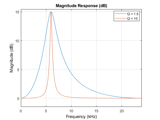
Q can be assigned values between 0.0001 ~ 1000, and higher Q values let you filter caught frequencies more sensitively. However, when filtering audio signals, if Q is too high it might sound unnatural and artificial rather than natural, so finding appropriate values is important.
Type
BiquadFilterNode can make various types of filters - they broadly divide into types that completely filter frequencies out, and types that can amplify or decrease specific frequencies.
Types that filter frequencies
lowpass (highcut): Filters out all frequencies higher than specified frequency.highpass (lowcut): Filters out all frequencies lower than specified frequency.bandpass: Filters out all frequencies except specified frequency.notch: Filters out specified frequency.
Types that amplify/decrease frequencies
lowshelf: Amplifies/decreases frequencies lower than specified frequency.highshelf: Amplifies/decreases frequencies higher than specified frequency.peaking: Amplifies/decreases specified frequency.
Among these, types that amplify/decrease frequencies can also be used in EQ (Equalizer) discussed below. This time I plan to make filters simply filtering frequencies, so I’ll implement filters using only types that filter frequencies.
I’ll implement a lowpass filter filtering all frequencies higher than specific frequency and a highpass filter filtering all frequencies lower than specific frequency. Let’s simply implement filters.
Implementing Filter
First use AudioContext object’s createBiquadFilter method to create BiquadFilterNode. Since my audio sample has 44,100Hz sample rate, I’ll set lowpass filter frequency to 1,000Hz and highpass filter frequency to 20,000Hz.
const lowpassFilterNode = audioContext.createBiquadFilter();
lowpassFilterNode.type = 'lowpass';
lowpassFilterNode.frequency.setValueAtTime(1000, audioContext.currentTime);

const highpassFilterNode = audioContext.createBiquadFilter();
highpassFilterNode.type = 'highpass';
highpassFilterNode.frequency.setValueAtTime(20000, audioContext.currentTime);
I didn’t separately set Q values, but that’s actually fine. BiquadFilterNode’s Q has default value 350 which isn’t too excessive or insufficient, so I’ll just use the default value. (Also a bit lazy.)
Now connecting the created filter nodes to the audio source lets you hear audio samples with frequencies below 1,000Hz and above 20,000Hz removed.
sourceNode.connect(lowpassFilterNode);
lowpassFilterNode.connect(highpassFilterNode);
highpassFilterNode.connect(audioContext.destination);
Those who’ve read this far probably started feeling, but actually HTML5 Audio API is so well made that developers barely need to touch anything. Before knowing BiquadFilterNode existed, I worried “wow how will I make this filter…?” but it was actually the one needing least worry. (So it was slightly anticlimactic.)
EQ
Equalizer (EQ) is an effector used for a kind of frequency equalization work (Frequency Equalizing) as the name suggests.
EQ is a basic effector laid down with compressors when mixing audio, mainly used to eliminate useless sounds from original sources and harmonize with other sounds. Since EQ is ultimately an effector controlling frequencies, it’s implemented using filters - since we’ve already made filters once, we can easily whip up EQ.
EQ broadly divides into two types: parametric equalizer and graphic equalizer - I plan to implement graphic equalizer among these. By the way, the image at top is parametric EQ, but I included it because the image looked cooler. For reference, graphic EQ looks like this:
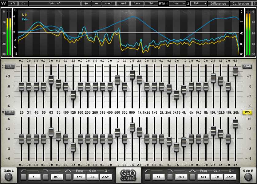 Graphic EQ visual exuding deep analog nostalgia
Both EQs have pros and cons - first, graphic EQ’s advantage is having more controllable frequency bands than parametric EQ and having an intuitive interface. You might say seeing the parametric EQ image attached at this paragraph’s top “huh? Parametric looks quite intuitive too?” - but originally hardware parametric EQ looked like this:
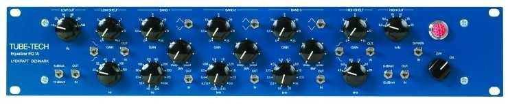 Black things are knobs. White things are numbers.
So graphic EQ is mainly used in places needing quick response like concert halls, and senior sound engineers with much experience have the scary skill of immediately catching the frequency when howling (sharp “screee-” sound sometimes in karaoke) occurs at concert halls and killing it with graphic EQ.
Graphic EQ’s disadvantages are that controllable frequency bands are fixed and fine frequency adjustment is difficult. Conversely, parametric EQ unlike graphic EQ can even set all controllable frequency bands.
However, simultaneously controllable frequency count is greatly lacking compared to graphic EQ. While typical parametric EQ can control 3-5 frequency bands, graphic EQ has experts with over 40 simultaneously controllable frequencies.
I think hardware parametric EQ’s maximum disadvantage is having a non-intuitive interface - this disadvantage is an area coverable with UI when implementing in software, and since most recording studios have situations where you can keep listening and equalizing rather than immediate response, many software EQs are implemented as parametric EQ with high freedom in frequency band control.
But in situations like the demo I’m making where I’m simply implementing, it’ll obviously be implemented with UI similar to hardware parametric EQ above, so I chose graphic EQ which is relatively easier to make UI for. (If you don’t understand this well, check the parametric EQ attached at the EQ chapter’s very top)
As mentioned once above, since EQ is implemented using filters, it’s not that complex. Let’s simply whip it up now.
Implementing Graphic EQ
If you saw the graphic EQ image above, you know this guy is equipment with fixed controllable frequency band counts. So I’ll also declare one array containing controllable frequencies and iterate this array while generating filters.
const frequencies = [
  25, 31, 40, 50, 63, 80, 100, 125, 160, 200,
  250, 315, 400, 500, 630, 800, 1000, 1250, 1600, 2000,
  2500, 3150, 4000, 5000, 6300, 8000, 10000, 12500, 16000, 20000
];
There’s a point to note here. Since EQ uses multiple filters, you must chain-connect each filter to each other. If filter gain is even slightly higher than 1, sound amplifies a bit each time passing through filters, and by the time it reaches your ears it becomes extremely loud sound that could permanently separate your eardrums.
🚨 Therefore you must set filters’ gain to 0 or below.
const inputNode = audioContext.createGain();
sourceNode.connect(inputNode);

const filters = frequencies.map((frequency, index, array) => {
  const filterNode = audioContext.createBiquadFilter();
  filterNode.gain.value = 0;
  filterNode.frequency.setValueAtTime(frequency, audioContext.currentTime);

  if (index === 0) {
    filterNode.type = 'lowshelf';
  }
  else if (index === array.length - 1) {
    filterNode.type = 'highshelf';
  }
  else {
    filterNode.type = 'peaking';
  }
  return filterNode;
});

filters.reduce((prev, current) => {
  prev.connect(current);
  return current;
}, inputNode);

const outputNode = audioContext.createGain();
filters[filters.length - 1].connect(outputNode);
outputNode.connect(audioContext.destination);
Looking at the if statement inside map method shows only the first and last filters getting different types - this is to cover all frequencies lower than first filter frequency and higher than last filter frequency using shelf type filters. (If you don’t remember filter types well, go back and see the Filter part)
Then chained all generated filters through reduce method and connected to outputNode too. Playing sourceNode after writing this far shows no changes.
Naturally since all filters’ gain is 0 there are no changes. Assigning random numbers between -1 ~ 1 to these filters’ values lets you hear sound change slightly. I personally recommend making it controllable by connecting with input[type="range"] elements to control filters’ gain and directly trying various things.
Also, since the lowest and highest frequency filters are set to shelf type, lowering these filters’ gain can also produce effects like lowpass or highpass filters.
Wrapping Up
So here we made commonly used effectors - compressor, reverb, delay, filter, EQ. Actually there are various other interesting effectors besides these 5, but I’ll stop here due to massive volume control failure.
As mentioned once when making filters, since HTML5 Audio API provides extremely high-level abstracted nodes, there’s actually not much for developers to directly implement. This also means detailed-level implementation is difficult, but since I’m not starting some audio effector company, it seems sufficient for making things just for fun.
Making various effectors like this brought back memories from when I worked as a sound engineer, and I had new things to learn about effectors too, so I had extremely fun working. Besides effectors written in the post, I plan to keep implementing various effectors, so interested people can look around my GitHub and send PRs. (Good things double when shared.)
That’s all for this post on making audio effectors with JavaScript - creating your own sound.
관련 포스팅 보�러가기
[Building JavaScript Audio Effectors] Understanding Audio Flow
Programming/AudioHow Do Computers Hear Sound?
Programming/Audio[JS Prototypes] Implementing Inheritance with Prototypes
Programming/JavaScriptBeyond Classes: A Complete Guide to JavaScript Prototypes
Programming/JavaScriptHeaps: Finding Min and Max Values Fast
Programming/Algorithm